Rather than calculating the air flow from the VE table and manifold pressure (MAP), you can use a mass air flow (MAF) sensor measure the amount of air directly. In some cases this can make the engine easier to tune, and better at adapting to changing engine parameters. On the other hand, the MAF sensor itself can present an significant airflow restriction to the engine (limiting power), and sometimes can have range limitations if the engine flow a lot more (or less) than the application it was designed for. This change and all others following apply to both MicroSquirt®.
Note that you should not use the automatic mixture correction option with MAF-Only, it will not work.
When the MAF-only option is selected with your MicroSquirt® EFI controller, the sensor would normally be wired to the MAP pin. If, however, the combined MAF/ MAP option is selected, then MAF MUST be connected to the Barometric/second EGO sensor pin (#29).
You can also use pin 5 of the Ampseal for MAF. Plus, if you have Frequency output MAF, you MUST use this pin because it is simultaneously tied to processor pin T7 which is the only timer pin that has a special read Frequency period mode, so it automates this process, making it much more accurate.
The MAF/ MAP blend option is used to cover the entire rpm/ load range with a high degree of resolution. Depending on the engine design, it may be that one or the other sensor is unsuitable for either the low end or the high end. By combining them, the entire range can be effectively covered. Perhaps more important, dual sensors are needed for observer/ model based tuning systems, where the two sensors plus a mathematical model of flow through the throttle plate are all used to provide a best prediction of engine performance. The prediction is self-correcting based on the sensor values. This use of two independent load sensors is common in most late model factory cars.
It is implemented by using:
If desired, the MAF/MAP blend operation can be reversed to use MAF at low rpm and MAP at high rpm. The logic is similar to the Alpha_N mode - in fact you can use a blend of all 3, although this option remains untested.
The Mass Air Flow (MAF) mode implemented in your MicroSquirt® controller uses the mass air flow rate signal obtained from an external MAF sensor to determine cylinder mass air, and determines a corresponding mass of fuel based on target lambda and the stoichiometric air/fuel (A/F) ratio of the fuel used.
If you select one of the MAF options, you must input a MAF sensor calibration curve (or use the default Ford curve). This is similar to the coolant sensor curve, in that both are non-linear and can not be handled as a simple scale and offset. The best way to obtain such a curve is by measuring the air flow through a flow bench. In doing this it is vital that the entire air duct be included in the measurement. If this is not feasible, then a shorter correction table is provided as a tuning input. This table consists of MAFFlow vs % correction arrays, where as usual 100% means no correction. The final MAF is calculated by:
To assist in the calibration and use of Mass Air Flow sensors, an analysis program has been developed to aid in the characterization of MAF transfer curves. This Windows program is called the MAF Analyzer and is available for download here:
To use the program, simply unzip in an empty directory and double-click on the application to execute - please read the user's manual for the MAF Analyzer included in the archive above. Below are some links for pre-run files that can be uploaded to your MicroSquirt® controller:
The default MAF sensor curve in your MicroSquirt® controller is for the Ford Lightning MAF. If you are using a any other mass air flow (MAF) sensor, you will have to calibrate your MicroSquirt® controller to read it correctly. If you are lucky, you may have one of the MAF sensors already programmed into TunerStudioMS.
If your sensor is not in TunerStudioMS's list, then you will need to create a 1024 element table of the air flow versus voltage. This file will be similar in format to the existing tables (see : maffactor_Q45.inc for an example), and you place this file in your project folder /inc/ sub-folder.
Then you need to open TunerStudioMS, and under 'Tools→Calibrate MAF Table' select your sensor and click the 'Write to Controller' button to burn the table. The table will stay in your MicroSquirt® controller's memory until you reburn it, or load new code.
Unfortunately it is nearly impossible to have a perfectly suitable 'default' MAF transfer map because of the sensitivity of installation to external factors.
For example, there are a bunch of different curves out there for the same 70mm MAF. We have the means to measure MAF sensors directly and compare it with an accurate laminar flow element to determine mass air flow. The problem is that when the MAF sensor is bolted to the vehicle none of the curves match (likely due to the inlet plumbing affecting the airflow).
The MAF ducting is important to its air flow/output voltage curve, yet very few aftermarket manufacturers know this. If you change any of the ducting, remove/add an air cleaner, or even put your hand in front of the airstream you will see a calibration change. You can see this just by running the engine at idle and remove the air cleaner or stick your hand in front of the airstream while watching the O2 readings. Idle (i.e. low mass air flow rates) region is most sensitive. In the end the curve measured on the bench with the actual inlet ducting is the most accurate but it still needs tweaking when installed in the vehicle.
MAF sensor measures air flow directly. So can we just plug it in and go?
For example, one vehicle was converted to V3 MicroSquirt in August 2011. It was originally a VAF (volume air flow) sensor car. Initially it was tuned to run very well with a MAP sensor. Then the OEM VAF sensor was replaced with Nissan Q45 MAF sensor. The target application had a 2.5l V6, versus the 4.5l V8 for the Nissan MAF sensor. In the new configuration, the inlet tract two ~90° bends between air cleaner and throttle body, with MAF in middle (see the picture below).
The latest code (3.770+) from B&G will generate a calculated 'MAP from MAF', and calculate 'MAF from MAP'. When 'MAF from MAP' agrees with the actual MAF sensor's corrected values, we have calibrated the MAF. We get them to agree by using the MAFcorr table to alter the MAF flow values ("mafSensor" as a gauge, "mafsensor" in the datalog) to match "MAF from MAP" gauge (also as "maf_frm_map" in the datalog). Once calibrated, the engine will run the same on MAF only or MAP only, and can be switched without noticing the difference.
Here are the MAF corrections required to get the corrected MAF output to match the calculated 'MAF from MAP' in the example vehicle using the correct Infiniti Q45 MAF file as a base curve:
100% is no correction, and the values needed range from 104% to 240%. That is 4% more airflow to 140% more airflow than an uncorrected MAF sensor curve.
Note that the biggest error is at the lowest flow (where the sensor likely never operates in the OEM application), the error is highly non-linear, but even the highest values have a +35% error (likely due to inlet ducting geometry).
There are a few lessons here:
The method above requires having a MAP sensor. If you don't have a MAP sensor installed, you will have to tune differently. To tune the MAF correction table without a MAP sensor, you need to know that a certain voltage output from the MAF means a specific grams of air per sec going through the MAF. You can get that from documentation or OEM curve provided the sensor location and ducting is exactly as it was stock from the factory or by having the MAF + ducting flowed or by using an accurate O2 sensor. So if you have a non-OEM setup you need to tweak the transfer function on the car.
In the case of having a non-OEM set-up, you start with some curve that will at least allow the car to run, then tuning the calibration curve to make the O2 reading match the target O2 reading. Do this for as many rpms as you require.
This is relatively easy with a narrow band exhaust gas oxygen sensor (or a wideband EGO sensor, just try to tune near the stoichiometric point to minimize errors). You can get a good feel for the accuracy of a MAF curve by using a cheap NB sensor. The NB is accurate because it limits itself to one point, and all you really need, for most purposes, is that 1 AFR point at a few different flows (rpms). Note that the correction can be 50% or more, especially at lower air flows.
Put the car in part/neutral and run the engine while monitoring the O2. Adjust the transfer function to get a stoichiometric mixture (i.e. 0.45 volts with a narrow band EGO sensor, or 14.5:1 AFR with a wideband EGO sensor/controller), then rev the engine up a bit and adjust the next bin. You will see a trend where it is good at low rpms but needs tweaking on the high end (or reverse). You can move the bins around to capture the place where it needs to be tweaked.
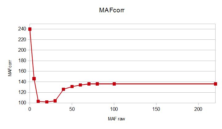
(Calibrated only to 140g/sec. Higher values extrapolated.)
If you have any questions or problems that can't be answered from the links above, or a search the MicroSquirt® manual:
you can ask questions at the MicroSquirt® support forum which is at: www.microsquirt.com Click the links for more information.
MegaSquirt® and MicroSquirt® controllers are experimental devices intended for educational purposes.
MegaSquirt® and MicroSquirt® controllers are not for sale or use on pollution controlled vehicles. Check the laws that apply in your locality to determine if using a MicroSquirt® or MicroSquirt® controller is legal for your application.
©2011 Bruce Bowling and Al Grippo. All rights reserved. MegaSquirt® and MicroSquirt® are registered trademarks. This document is solely for the support of V3 MicroSquirt® boards from Bowling and Grippo.