
Many ignition modules (aka. "igniters") and some coils with built in igniters require a 'logic level' signal. Generally this means a 0 or 5 Volt signal that changes from one of these levels to the other at appropriate times (generally to initiate dwell and spark).
Your V3 MicroSquirt® controller can only supply a logic-level output. It will not directly control a coil, for example.
What this means is that the V3 MicroSquirt® will provide a 0-5 volt signal output of low current which is then used to trigger an external driver module/igniter. The MicroSquirt® documentation outlines several driver modules that can be used and how to hook them up. For example, the Bosch "211" igntion control module works really well. You can also use external BIP-373 drivers on your own board to drive the coils. Alternately, ignition coils with the built-in igniters (like the LS1/LS2 coils) work great without a module. These coils can be connected directly to the logic-level outputs, and this really makes the installation robust and easy.
Those using Ford's EDIS wasted-spark ignition system can use logic-level signal with no changes.
In some cases, you may need to tie the ignition outputs together (with a M-0 crank wheel and cam sync controlling a distributor, for example).
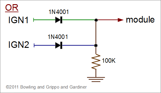
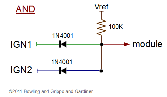
In all cases where outputs are tied together, you must join only the outputs from the FET drivers, which are in a wired-or configuration. NEVER join the 2 processor outputs directly together. If it is necessary to combine the signals, they must go into a logic AND or OR chip/circuit. The circuit will prevent the ignition outputs from short-circuiting the processor outputs when one is trying to pull the signal high, and the other is trying to pull the signal low.
Here is an example of a logic OR circuit (high if either IGN1 or IGN2 are high, low otherwise; use if the dwell period of the signal needs to be high):

Here is an example of a logic AND circuit (high only if both IGN1 or IGN2 are high, low otherwise; use if the dwell period of the signal needs to be low):
