Click on our menu buttons immediately below to find MegaSquirt® information quickly:
MicroSquirt® Module
V1/V2 MicroSquirt®
Important Safety Information
MicroSquirt® Support Forum
- MShift™ TCU
- MShift™ Intro
- GPIO Build Guide for 4L60E
- Base circuits
- GPO1, GPO2, GPO3,
GPO4 (gear LEDs)
- VB1, VB2, VB3, VB4
- PWM1, PWM2, PWM3, PWM4
- GPI1, GPI2, GPI5
(2/4WD, Input2, downshift)
- GPI3 (Temperature)
- GPI4 (Brake sense)
- EGT1, EGT2, EGT3,
EGT4 (non-CAN Load, line pressure, Input3, Input1)
- VR1 (Vehicle
Speed Sensor)
- VR2 (Upshift button)
- Finishing Touches
- Testing your
GPIO Board
- External Wiring Guide for 4L60E
- Current Release Code
- User Settings
- βeta Code
- Code Archives
- Purchase a
GPIO kit
- Working with the Shift Table
- Serial
Connection Troubleshooting
- CANbus
Set-Up
- Solving VSS
Issues
- Ports, pins, circuits, connections
- MShift™ Discussion
Forums
- Misc. MShift™
Topics
- MShift™ sitemap
- Template Project Code
- GPIO Board Intro
- MShift™/GPIO
Support Forum
|
TFI Ignition Control
Thick Film Ignition (TFI) modules were used on Ford vehicles with distributors from the early 1980s to the mid-1990s. It was used on a number of Ford's engines, the EFI 5.0 engines in particular. The TFI module is a gray box fitted to the side of the distributor. It is about one inch wide, and about four inches long. The distributor itself uses a Hall effect sensor.
The TFI modules are available as Holley 891-105 or Accel 35368 (~$46), as well as from a number of aftermarket sources.
Installing the Ford TFI System
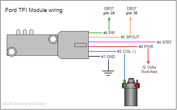
Note: this information is tentative. The TFI setup has not been 100% verified yet.
First, be sure to use MicroSquirt code version 2.1 or higher. This code has the appropriate algorithm for the necessary 'trigger return' cranking parameter. Get the code here.
To install TFI with MicroSquirt, you:
- Use the OPTO input circuit
(Substitute OPTOIN (Amp pin #30) for DB37 pin 24, and IGN1 (Amp #12) for DB37 pin 36 in the diagram above)
Note that the jumper goes to the via marked S12 on the top side of the board. Some PCBs may have a slightly different layout, in all cases you should check for 12 volts (nominal, actual voltage depends on the power supply voltage) at the end of the resistor that doesn't connect to the IGN/IGBTOUT jumper.
The PIP signal comes into MicroSquirt on Ampseal pin 30, the SPOUT goes out on pin #12.
Then in TunerStudio, set:
- Trigger offset = 10° (this will vary, depending on the distributor orientation),
- Ignition Input Capture to 'Falling Edge',
- Cranking Trigger to 'Trigger Rise',
- Coil Charging Scheme to 'Standard Coil Charging',
- Spark Output to 'Going High (Inverted)', ('Going High (Inverted)' for MicroSquirt).
Then set the maximum dwell duration to 8.0 milliseconds with no battery voltage compensation (set the five 'Duration at Voltage X' to 0.0 under 'Dwell Settings/Battery Voltage Compensation' in MegaTune.).
MegaSquirt® and MicroSquirt® controllers are experimental devices intended for educational purposes.
MegaSquirt® and MicroSquirt® controllers are not for sale or use on pollution controlled vehicles. Check the laws that apply in your locality to determine if using a MegaSquirt® or MicroSquirt® controller is legal for your application.
©2005, 2007 Bruce Bowling and Al Grippo. All rights reserved. MegaSquirt® and MicroSquirt® are registered trademarks. This document is solely for the support of MegaSquirt® boards from Bowling and Grippo.